I’ve been having fun watching the math that Mike Lawler (@mikeandallie on Twitter) and his kids discuss on video at their blog mikesmathpage, and thinking about how to get my own 8-year-old son interested in watching those videos. Their post from yesterday, Penrose tiles and some simple 3D variations, has three great videos that are very visual and so I started with those. In these videos Mike and his kids examine various tilings of 2-dimensional space and various tessellations of 3D-space, using the following models:
- AspiringEdifier’s Penrose Tiles (kite and dart)
- richgain’s Apparently Impossible Cube
- our Rhombic Dodecahedron wireframe model (Day 210)
Much thanks to Mike and his kids for making their mathematical journey available for others to learn from, and also for using our models as part of their explorations!
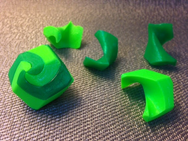
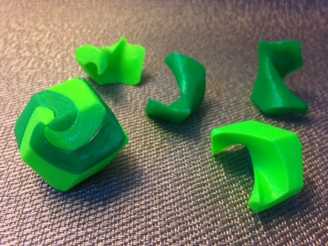
In the second video, Mike and his kids show that two very odd shapes can be used to fill 3-space because pairs of them can combine to make a cube, which of course fills space. In their third video they use 3D-printed models and ZomeTools to show that Rhombic Dodecahedra also fill space. The following model combines these two ideas, using four copies of an even stranger object to construct a Rhombic Dodeahedron:
- VeryWetPaint’s Puzzle Rhombic Dodecahedron
And that’s the weird squiggle that we’ll be filling space with today:
Thingiverse link: http://www.thingiverse.com/make:71484
Settings: Printed on a Replicator 2 with raft but no supports, on a glass platform with blue painter’s tape, at 80% scale, with two pieces of each color. On .3mm/low the pieces took about 12 minutes each to print and made a model was very tight and difficult to assemble, and nearly impossible to take apart. On .2mm/low the pieces took about 16 minutes each to print and have the same problem. Hopefully the clearance will loosen up with repeated use, but if not then I will try to figure out the OpenSCAD code that made this model so that I can increase the clearance.
Technical notes, OpenSCAD flavor: VeryWetPaint made their code available and I’m going to attempt to annotate it to make clear how it works. To understand this code you’ll need to learn about Minkowski sums and .dxf extrusion in OpenSCAD. Here are some things I don’t understand yet about this code: (1) why does it seem like the two helical pieces that are removed in the “difference” operation are so different, and (2) how was the .dxf file made and what is the equation for whatever that helix is? I’ll update later if I figure it out; please comment below if you know!


The two helical subtractions aren't actually different, that's just an unnecessary distraction. My original spiral.dxf had been created for making a trisection, so it was optimized for a script to subtract 240 degrees (2/3 of a revolution). The extra subtraction removed a further 30 degrees to bring the total to 270 degrees (3/4 of a revolution).
For your benefit I incorporated your comments, simplified the script and DXF file, and uploaded new versions to Thingiverse as Rhombic270.scad and Spiral270.dxf. It generates exactly the same STL with a single twisted extrusion, so it should be easier to figure out what's really happening.
To assist you in understanding how it works, I offer the following OpenSCAD script that demonstrates what happens if Spiral270.dxf is intersected with a circular ring. It demonstrates how this new Spiral270.dxf covers a 270-degree arc at every radius, yet each arc is slightly different depending upon its radius. (ie: distance from the origin)
// choose an inner radius from 1-25
radius=10;
// intersect a ring of the specified radius with the spiral figure
// (result will be a 270-degree arc)
intersection()
{
difference() { circle(radius+1); circle(radius); } // makes a circular ring
import( "spiral270.dxf" ); // the spiral drawing
}