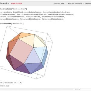
This is the second in a series of posts that walk through the 3D design construction of some Polyhedral Light String Ornaments. In our previous post we covered Step 1, using the PolyhedralData package in Mathematica to create and export an STL file of a Snub Cube. In this step we’ll scale that Snub Cube to “ornament size.”
In case you want to jump in and play along but don’t have the file from the previous step, here is a link to the file we’ll be starting with:
Snub Cube from Step 1: http://www.geekhaus.com/hacktastic_files/SnubCube.stl
In the second step of our design path, we will use Tinkercad to scale this Snub Cube. Along the way we’ll have a chance to learn about Tinkercad’s importing, scaling, and the Ruler and Align tools. Tinkercad is one of the simplest ways to make or modify 3D models, so no matter how much of a beginner you are, this step is a good place to start. Let’s go!
Step 2. Scale the model using Tinkercad
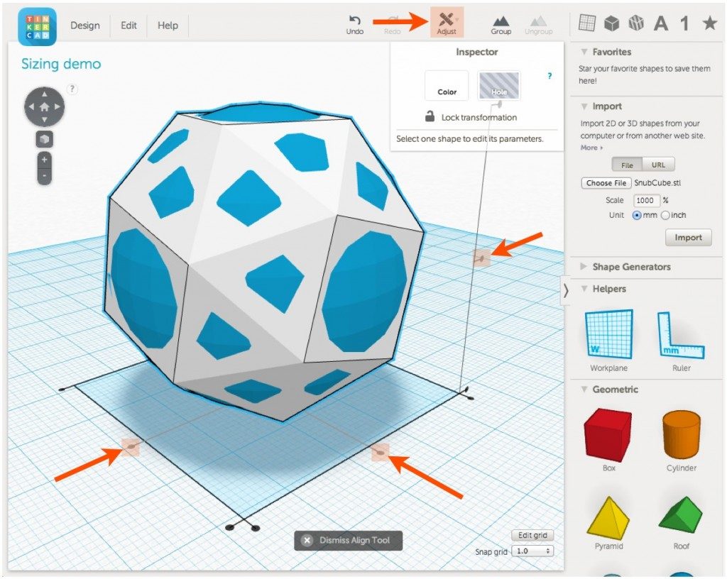
To import our model into Tinkercad we use the “Import” tab in the right-hand menu. Choose the file from your computer and then set the scale. The model we are importing is less than three millimeters across, so to make it more managable we’ll set the scale to 1000% (that sounds crazy but it’s just 10 times the size — because 100% would be no change in size, and 1000% = 10 x 100%). See the red arrows in the screenshot below.

Now look at the purple arrows in the screenshot. The “Helpers” tab in the right-hand menu contains a “Ruler” tool. To use the Ruler, place it anywhere on the blue-grid Workplane. We put it in the lower left corner. When the Ruler is on the Workplane, any object that you select will have visible x, y, and z dimension numbers. In fact, you can modify those dimensions simply by selecting those numbers and typing in new ones. We’re not going to need that functionality right now, but it’s a valuable thing to know about the Ruler for other situations.
The object we are designing will be part of a set of polyhedral ornaments, and we would like of all of the ornaments to be approximately the same size. Using a set of calipers, we settled on a diameter of 42mm, because 42 is the most important number (but not the highest number). Because polyhedra can have very different shapes, we can’t necessarily make them have “matching sizes” by making one of their x, y, or z dimensions equal to 42mm. Instead, we’ll scale by making each polyhedron look as much like a 42mm sphere as possible. That won’t be precise either, but it will make each one polyhedron have about the same size-feeling as every other.
Using the “Geometric” tab in the right-hand menu, select and place a Sphere onto the Workplane. By shift-dragging from a corner (or by typing in the numbers!), resize the sphere to be 42mm in diameter all around. Pressing shift while dragging the corner will insure that all dimensions of an object get scaled at the same time, and therefore that the object does not change shape. See the red arrows in the screenshot below.

Now we’ll resize the white Snub Cube so that it has about the same heft as the blue sphere. Shift-scale the Snub Cube until it looks like it is about the right size, and then use the Adjust/Align tool to center the two objects and compare. To do this, first select both objects at the same time (either by window-dragging a region around both objects or by click-selecting one and then holding Shift while click-selecting the other). Then choose “Adjust” from the top menu bar and “Align” from its drop-down menu. This will produce three alignment bars in the x, y, and z directions, each with endpoint and center alignment dots. Click on all three of the center alignment dots so that the two objects are aligned in each direction; the three dots are indicated by red arrows in the screenshot below. Note that you may have to move your viewpoint to see all three of the alignment dots; to do this, right-click a point on the Workplane and drag your mouse to rotate the view. (While we’re one the subject, you can also drag, or “pan”, the view by Shift-right-clicking and dragging.)

If the size of your Snub Cube doesn’t seem right after alignment then resize it and align again to compare. We usually resize until the sphere is poking through almost to the edges of one type of face on the polyhedron, as shown above. When you’ve got your Snub Cube sized the way you want it, you can select and delete the blue sphere.
To export the resized model, choose the “Design” menu tab from the upper right of the screen and then “Download for 3D Printing” from the dropdown menu. (Notice that you can also download .schematic files for Minecraft, send your model to be 3D printed at a number of partner sites, or send it directly to Thingiverse!)

This menu selection will open up a new window where you can choose a desired file format. We usually choose STL format, since that is what we need to send to the 3D printer. However, in this case we’ll be choosing OBJ, because our next stop will be importing this model into TopMod, which requires OBJ format.

That’s it for Step 2! Although we took our time going through each step very carefully, resizing in Tinkercad is a pretty fast and easy process. Notice that we just described three ways to resize an object in Tinkercad: by changing the scale during the import process, by shift-dragging a corner, and by typing in numbers with the help of the Ruler tool.
In case you had trouble importing files into Tinkercad or getting started, here is a link to the Tinkercad design we’ve been working with in this post:
Link to Tinkercad sizing demo: https://www.tinkercad.com/things/dgxLiQ4vLO5-sizing-demo
And in case the Tinkercad servers were down today, or in case you had some other problem or followed along in your mind only, here is a link to the scaled OBJ Snub Cube file that results from the process above.
Snub Cube at end of Step 2: http://www.geekhaus.com/hacktastic_files/SnubCube-scaled.obj
In MeshLab our object now looks like this:

Nothing surprising here; everything looks the same as it did in the last post except that the diameter line shown in the figure is now about 43.5 millimeters instead of just 2.5. For the record, we could have scaled this object in MeshLab very easily without going to Tinkercad at all, but only if we knew what length we wanted that diameter to be in the first place. For creating a set of objects whose size is aesthetically rather than precisely determined, I prefer to work in the visual world of Tinkercad.
Next time, Step 3: In which we use TopMod to pretty up our ornament and invent the word “instellate”…
UPDATE: By “next time” I mean “later”. A job change and other craziness kept me from writing Parts 3 and 4 of this post, and now I want to move on to some other things. Let’s return to this project later…
——————
As an Amazon Associate we earn from qualifying purchases, so if you’ve got something you need to pick up anyway, going to Amazon through this link will help us keep Hacktastic running. Thanks! :)

Leave a Reply