Today’s post is contributed by Bill Owens, also known as owens on Thingiverse. He is the creator of the Customizable Menger Sponge and Customizable Sierpinski Tetrix models that cleverly print without support due to the help of some custom stands that print with the models. Thank you, owens, for being our first guest blogger!
I just published a model of a Tetrahemihexahedron on Thingiverse. It is a cool-looking but fairly simple polyhedron, with just six vertices that it shares with the octahedron, but it’s a nice object to be able to model and hold in your hands in order to really understand its shape. And it has an interesting property that makes it more challenging to model than most polyhedra.
Thingiverse link: http://www.thingiverse.com/thing:269732
Settings: Cura with .3 mm layers, 10% infill, 0.8 mm shells (two layers), 0.6 mm top/bottom (also two layers) and cooling fan at full, on our OB1.4 with 1.75 mm PLA and a heated glass bed. No supports or raft are needed, but with a non-heated bed I’d recommend a brim if printing on the hollow side.
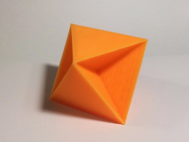
Technical notes, math flavor: The key thing to know about the Tetrahemihexahedron is that it only has seven sides, despite how it looks in the picture above. Four sides are equilateral triangles, and the other three are squares; you can see one of them if you look straight at any of the vertices. Each square goes through the center of the object, and all three of them cross each other but those crossings don’t constitute edges; the squares are still squares, not cut into triangles. This makes the Tetrahemihexahedron an object that can’t really exist in 3-space, in some ways analogous to the Klein surface (aka the Klein bottle) whose neck has to pass through its side in order to connect back to itself.
Technical notes, OpenSCAD flavor: Despite the impossibility of this object existing in 3-space, it is possible to make a model of it, by accepting that the squares actually will intersect and we’ll just have to pretend that they don’t. So to create it I started with the vertices of an octahedron, generated by referencing the square pyramids from Day 184. I laid out the four equilateral triangles and the three squares, and asked OpenSCAD to render the model. It told me that some of my faces weren’t laid out correctly; in order to render the model with the correct appearance, it needs to have the vertices of each face in clockwise order when viewed from the outside. That’s not an uncommon mistake for me, and I jumped right to the always-handy View:Thrown Together mode; if you have any bad faces, it will color them pink so you know what to fix. Unfortunately, what I discovered is that each of the squares was both good and bad. Taking the square in the XY plane as an example, when viewed from above (+Z) the vertices were clockwise and the face was fine. But that same square was also visible from below (-Z) and from that perspective it was backwards, with counterclockwise vertices.
There was clearly no way to fix this problem, so I decided to cheat a little and break up each square into four right triangles. I methodically redid the vertices, making sure that each one was clockwise from the outside, and finally OpenSCAD would render the object. Then I tried to export it to STL, and received a much more serious error: it was not a manifold object.
For OpenSCAD, being manifold means that the object has no holes (it would hold water), and that the object has at most two faces connected along an edge. Because of the way I broke up the triangles, my object had four faces along each of the edges that met in the center. Obviously that had to change.
The first step to fixing this problem was a realization that if I wasn’t trying to make a perfect model I didn’t really have to use all of the vertices. In fact, I only had to model one quarter of the object, and duplicate that small tetrahedron with the appropriate rotation.
module onetetra() {
polyhedron(
points = [
[0.5,0.5,0], // 0
[-0.5,0.5,0], // 1
[0,0,1/sqrt(2)], // 2 (top vertex)
[0,0,0], // 3 (center)
],
triangles = [
[0,2,1],
[0,1,3],
[0,3,2],
[1,2,3],
]);
}
module tetrahemihexahedron() {
union() {
onetetra();
rotate(180,[0,0,1]) onetetra();
rotate(180,[1,1,0]) onetetra();
rotate(180,[-1,1,0]) onetetra();
}
But once again, I’d produced a non-manifold object. The simplest way around that was to add fillets, in this case tiny rectangles that would run along the intersection and break it up, so each visible face connected only to the fillet, and nothing connected at the actual intersection.
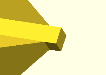
Making a long, skinny cube to be a fillet was also easy, but that created one more problem. In order to completely eliminate the bad intersection the fillet had to extend all the way out to each vertex, but that meant the corners of the fillet would hang over and extend past the edge of the model.
Appearance-wise this wasn’t great, but it would also cause problems for printing because the tiny corners of the fillet would effectively lift the model off the printbed, and make the first layer consist of just three tiny points.
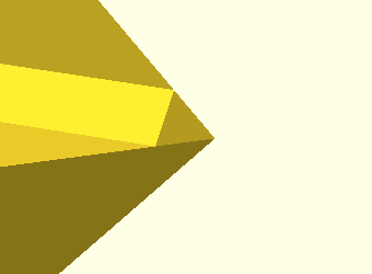
To solve that, I first tried trimming the fillet cube with a much larger cube turned on its corner, but of course that wasn’t exactly right. Then I tried a cone, to make the fillet look as though it had been sharpened like a pencil, but it still stuck out. Finally I realized that the right answer was a simple octahedron, the one whose vertices I’d started with; once I used that to remove the corners of the fillet, it lined up perfectly.
The finished model looks pretty good even in the OpenSCAD rendering, with the fillets just barely apparent. Because of the limitations of 3D printers, they completely vanish from the final print. I encourage you to print your own, and to get a better feel for this curious little polyhedron.
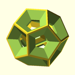
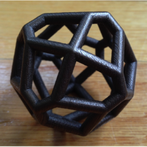
UPDATE: Owens has now published new models of the Stewart B4,3 and B4,4 polyhedra to Thingiverse that have the same type of impossible square-face intersections as this Tetrahemihexahedron.

Leave a Reply