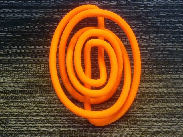
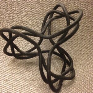
This semester five students and I have been 3D-printing the knots through 7 crossings in both standard and special configurations, as part of our MATH 297 – Knot Theory Research and 3D Printing course in the JMU 3-SPACE classroom. One of the knots that fell to me was 7_6, which happens to be the spiral knot S(5,2,(1,1,-1,1)). This means that it can be represented as a braid that has 5 strands, one of which crosses the others in an “over, over, under, over” pattern for a repeat of 2 times; or in other words, that the knot can be obtained with braid word (abCd)^2. All that is nice, but for the purposes of this post all that matters is that the knot 7_6 can look all spirally like it does in this picture:
Thingiverse link: http://www.thingiverse.com/thing:304206
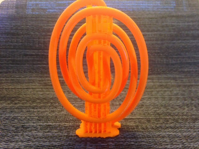
Settings: Printed on a Replicator 2 with our custom MakerWare support profile for knots from Day 110. The model has so many long pieces that if you orient vertically as in the picture below, you can get away with almost no support at all. This is the least amount of support I have ever had for any knot!
Technical notes, TopMod flavor: I am very excited to report that I actually constructed this knot by hand, one arc at a time, in TopMod. Although I did make the knot from Day 137 with TopMod, I was not trying to make that particular knot; this is the first time that I had a certain knot in mind and then constructed it in TopMod, rather than with equations or data. The reason I did that is that I don’t know the equations or have any data for the spiral conformation of 7_6; I just knew what it was supposed to look like! In case anyone out there is interested in using TopMod to construct knots, here is a step-by-step breakdown of what I did, starting with a 2-dimensional projection of the conformation I wanted to build:
- Open TopMod and click on the cube to put down one box.
- Select a face of the box and use the Cubical Extrude button to extend into a connected line of boxes (I used x50 to get a line that was 50 blocks long). In the 7_6 spiral case I knew that all of the crossings would end up on one line so that was all I needed to get started. For other knots and other conformations you’ll have to use Cubical Extrude to build a branching framework to build from.
- Use Selection/Edge Ring to select boxes to delete from your row. I deleted two boxes between every one box that I wanted to keep, plus a few more for the center. After deleting I had six separated boxes in a line, followed by a gap, followed by six more separated boxes.
- Select the tops of all your boxes and Cubical Extrude x8 to get some height. You will be connecting boxes at various heights to make the arcs between each crossing in your knot projection.
- Make the arcs of your knot by connecting faces of boxes as desired with the Add Handle (Shape Interpolation) Mode button. As part of this you will have to adjust the number of segments (for a finer or coarser look) and the weight (to determine the curvature of the connecting handle). When you select two faces to connect with a handle you will also select a corner on each face, which will determine how twisty the connecting handle is. You can also manually set the number of twists if desired.
- Once all your arcs are in place, delete any unneeded cubes using Selection/Edge Ring and the wonderful tool “=“, which expands a selection outward one step at a time.
- You should now have a choppy-looking curve in the desired conformation of your knot. Use Remeshing/Corner Cutting twice to get a smoother knot model.
- Export to STL; this may take a minute because TopMod will have to further refine your mesh to be triangular as it is performing this export.
Technical notes, Blender flavor: The knot produced by the method above had fairly thin strands, so to thicken them up I used Blender. Although one of our lab students wrote the excellent post Adding Thickness to your STL file at the MakerLab blog last December, I had not used this method until today. I also consulted the Interface and Navigation video at BlenderCookie to learn how to move around: scroll wheel to zoom, middle-click and drag to rotate view, and shift-middle-click and drag to pan view.
- A new “starting document” in Blender will contain a camera, light, and cube, which I wasn’t sure what to do with. For the moment I learned how to hide them: in the upper right “Scenes” box, deselect the eye, arrow, and camera icons for all three.
- File/Import/STL and choose the file you want to open. You may have to zoom out a lot to see your model.
- Under the “Scenes” box in the right column, choose the “wrench” icon to get to Object Modifiers. You may have to expand the width of the right column to see the wrench icon.
- Choose Add Modifier/Solidify with Thick changed to 2 and Offset to 0. Pressing return after setting the offset performs the action so you do not need to click “Apply”.
- Export your new, thickened STL file.
Leave a Reply